CW DC Transceiver Type 002
Direct-conversion transceiver for amateur radio
DL6ZB, Rolf Heine
1. Receiver
| Band | 40 m (7 MHz) |
|---|---|
| Mode | CW, full break-in (QSK) |
| Output power | approx. 1 W |
| Receiver | direct conversion, diode ring mixer, 0.5–1.5 kHz L/C Chebyshev AF filter |
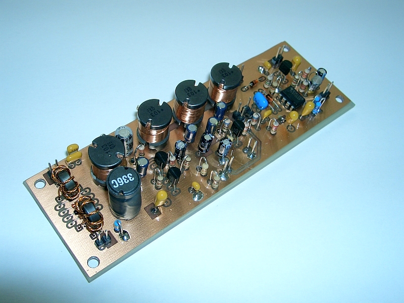
This is the Type 002 DC receiver of my 002 transceiver project. It uses an L/C Chebyshev filter optimized for CW. The muting of this DC receiver design is suitable for full break-in (QSK).
Some builders would choose a 4066 CMOS switching mixer, but I prefer diode ring mixers because of their simple broadband design. Just connect a VFO with +7 dBm output to the ring mixer. A receiver like this certainly needs a bandpass input filter or preselector. A preamplifier helps isolate the VFO signal from the antenna, although the diode ring mixer already attenuates it by at least 35 dB.
The L/C Chebyshev bandpass filter covers 0.5–1.5 kHz with a flat insertion loss. It has 50-ohm input and output impedances. This design allows the use of readily available 10 mH inductors. After various tests, I found that a −3 dB AF bandwidth of 1 kHz is fine for most conditions on 40 m. I may add an active narrow-bandwidth filter after the last AF stage in the next design step, although I'm satisfied with the current design.
The noise figure of the first AF stage is about 2.3 dB, which is sufficient to detect even weak signals. A 2N4124 would offer a somewhat lower noise figure, although in my opinion that isn't really necessary on the lower HF bands. This receiver really "hears" everything! Nothing more is needed. The "capacitance multiplier" T6 helps clean up the supply current for the first AF stage. The capacitor C15 (22 µF) is multiplied by the current gain of transistor T4. This easy trick of decoupling the power supply from the first AF stage, first used by W7EL, is very helpful in preventing hum.
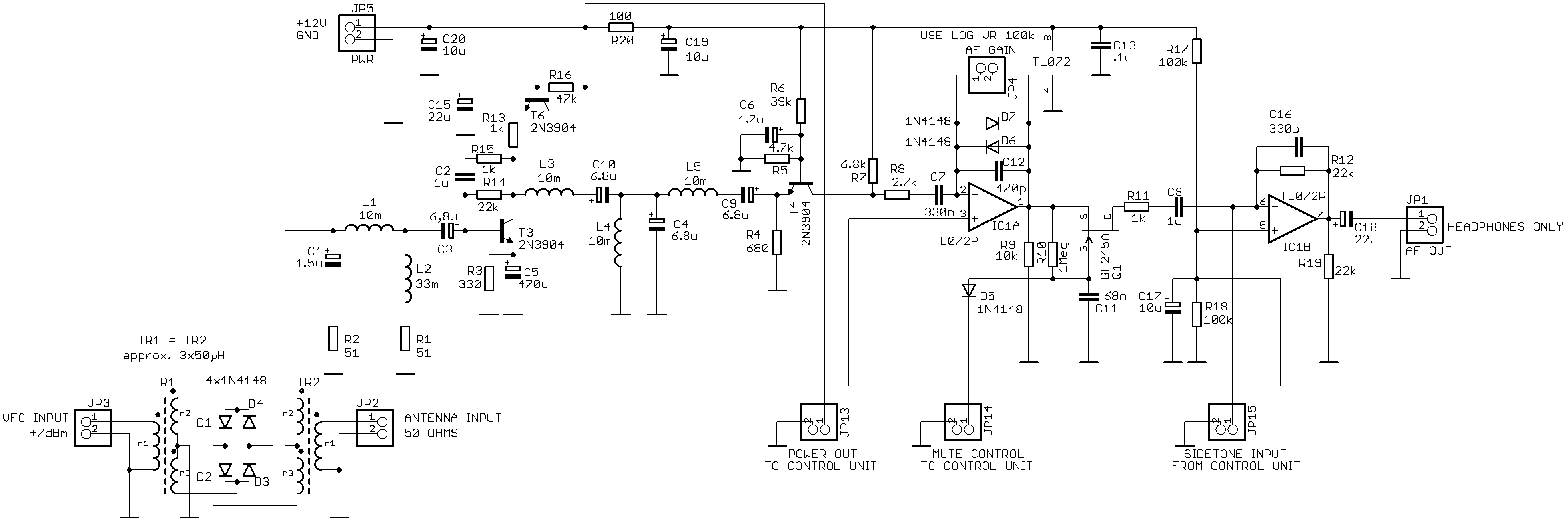
Toroids for the diode ring mixer: trifilar, 3 × 50 µH, wound on Amidon FT37-77 cores; 50 µH = 8 turns.
2. QRP Transmitter for 7 MHz
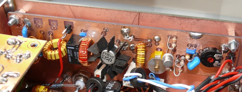
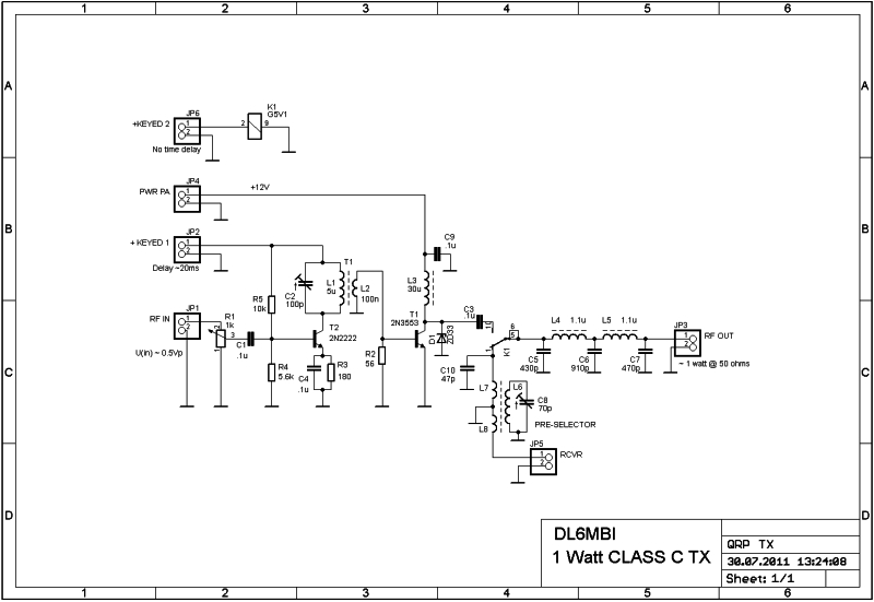
The QRP transmitter delivers approx. 1 watt of RF output. Alignment is as simple as the circuit. There are two adjustment points:
a) Adjust C2 for maximum output power.
b) Adjust R1 for about 1 watt output.
What can you expect from this transmitter? In short: distances of up to about 500 km during the day and 1,500 km at night with wire antennas. Typical signal reports are 539 to 579. Do not expect DX, although it may be possible with good antennas and good conditions.
Transceiver Performance
In one word: amazing!
It's hard to believe that such a simple receiver design can clearly pick up signals from all over the world, while the transmitter has earned praise from most QSO partners.
AM breakthrough can be prevented with a simple bandpass filter or a preselector between the antenna and the receiver RF input. Without a preselector or bandpass filter, AM breakthrough may occur, because every possible signal reaches the antenna input, which is a very extreme condition for any receiver – even the best!
A word about hum: builders of DC receivers must take care to avoid hum. Proper shielding of the VFO in a metal housing and good grounding techniques are essential. Avoid mains power supplies whenever possible; batteries are definitely the better choice. I use a sealed 12 V, 4.5 Ah lead-acid battery, which I bought from a local dealer (Pollin Electronic, www.pollin.de). It lasts for a couple of evenings of operation.
If low-impedance headphones are used, some hum may be noticed because of higher currents in the unavoidable ground loops. I usually use ancient high-impedance headphones from Sennheiser. When I compared a readily available pair of low-impedance headphones with the high-impedance Sennheiser model, I noticed very little hum with the antenna disconnected, as expected. After reconnecting the antenna, there was no hum at all, because the shortwave noise simply covered it.
Even weak signals always sound clean, with the typical hi-fi sound of these tiny DC receivers.
Below are pictures of my homebrew 40 m full break-in DC transceiver.
RF output: 1 watt.
It's a prototype in a modest housing made of copper-clad board. The transceiver will be moved into a new housing after an "evaluation period."
Latest improvements:
- Logarithmic S-meter amplifier (SA614)
- VSWR indicator
- Planetary gear for frequency tuning
- Simple mechanical frequency display
Click on the picture for better resolution.
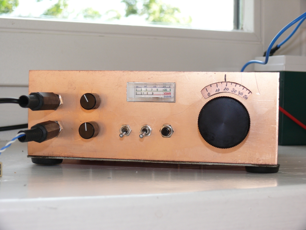
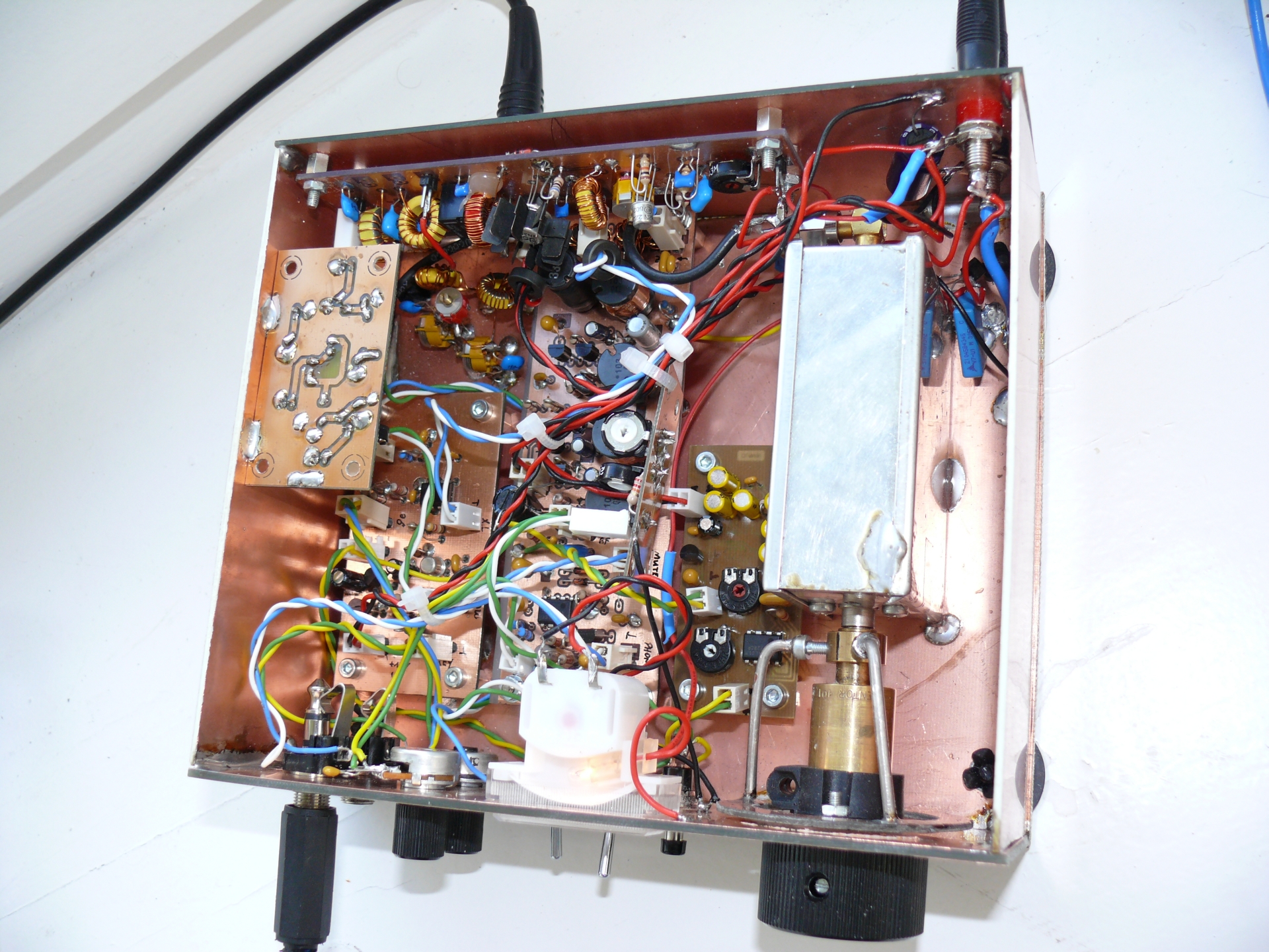
The transceiver described here was inspired by W7EL's "Optimized QRP Transceiver," which I had built before, although I made significant changes to the front end and the 50-ohm post-mixer amplifiers/filters.
40 m CW QRP Transceiver – Prototype
(DL6MBI, June 24, 2011)
From right to left:
- VFO, 7.0–7.2 MHz
- S-meter amplifier
- DC receiver
- Control, RX/TX/RIT
- Directional coupler (top)
- Rear: transmitter, 1 watt output
- S-meter scale made with a simple printer; the S-meter is quite accurate
- AF gain, RIT, switch for VSWR/S-meter, "ZERO" frequency button
- Planetary-gear-driven frequency display