Icom IC-730 CW Filter
An alternative 455 kHz CW filter for the famous classic Icom transceiver
Rolf Heine, DL6ZB
Abstract
It's a shame, folks. The gold rush is on, and prices for used CW filters these days are through the roof. So the cost-conscious homebrewer needs to get creative. Why not use IF filters that are available in sufficient quantities at fair prices?
Using the example of the more than 40-year-old Icom IC-730 transceiver, I'd like to show how to add a 455 kHz CW filter. Originally, this transceiver was not designed for narrowband 455 kHz CW filters, so a few small circuit changes are necessary. But don't worry, the changes are minor. Still, the OM/YL will need to pick up the soldering iron, because a few components are needed for the new filter.
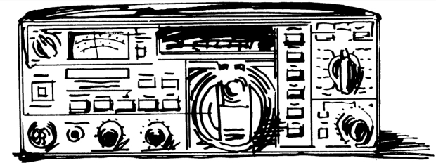
This transceiver is legendary for its excellent receiver and its punchy DX audio thanks to a true IF speech processor. Even today, in the well-known Sherwood list, this aging transceiver outperforms much more famous rigs. That's no wonder, because the circuit, as any knowledgeable person will immediately recognize, shows the pronounced sophistication and expertise of the engineers of that time. In short, the radio is worth a closer look. Incidentally, this transceiver embodies a timeless design that has not lost any of its charm after more than 40 years. Who would have thought that this Icom design from the late '70s would stand the test of time so well?
The problem arises when you want to buy accessories for the radio. After such a long time, there is no support from the manufacturer. The CW IF filter in particular is now worth its weight in gold. Opportunists take advantage of the shortage for their dubious dealings. So solutions are needed.
Which Filters Are Worth Considering?
One solution is simply to buy used filters from other manufacturers. Just plugging them into the transceiver is not possible, because the CW filters intended for this transceiver are the FL-45 and FL-54 types for an IF of 9.0115 MHz – unfortunately an odd and tricky frequency for which no other filters exist.
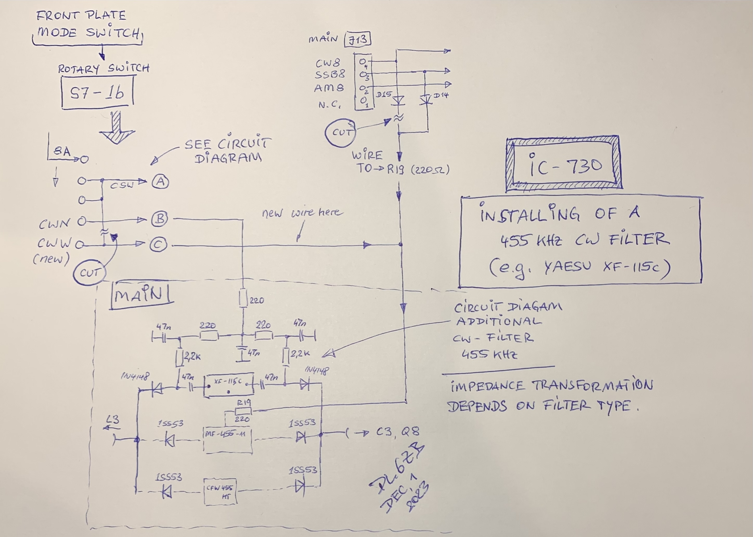
So why not get around the problem by using the 3rd IF (455 kHz)? For 455 kHz, there are still relatively inexpensive filters from various manufacturers on the market. A few additional components, rewiring the mode switch on the front panel in two places, two control wires, and two short pieces of coaxial cable – and you've saved money and found an excellent solution. On top of that, the CW filter in the 3rd IF allows even better use of the IF shift. And since the 455 kHz filter is still ahead of the AGC detector, the user gets all the advantages.
Crosstalk between the input and output of IF filters is much lower at 455 kHz than at the 2nd IF of 9 MHz. Matching is easier, because many of the available 455 kHz filters have similar impedances. The insertion loss of 455 kHz filters is usually slightly lower, and the shape factor is better than that of filters at much higher frequencies.
Watch a video showing how it works on YouTube.
About the Circuit
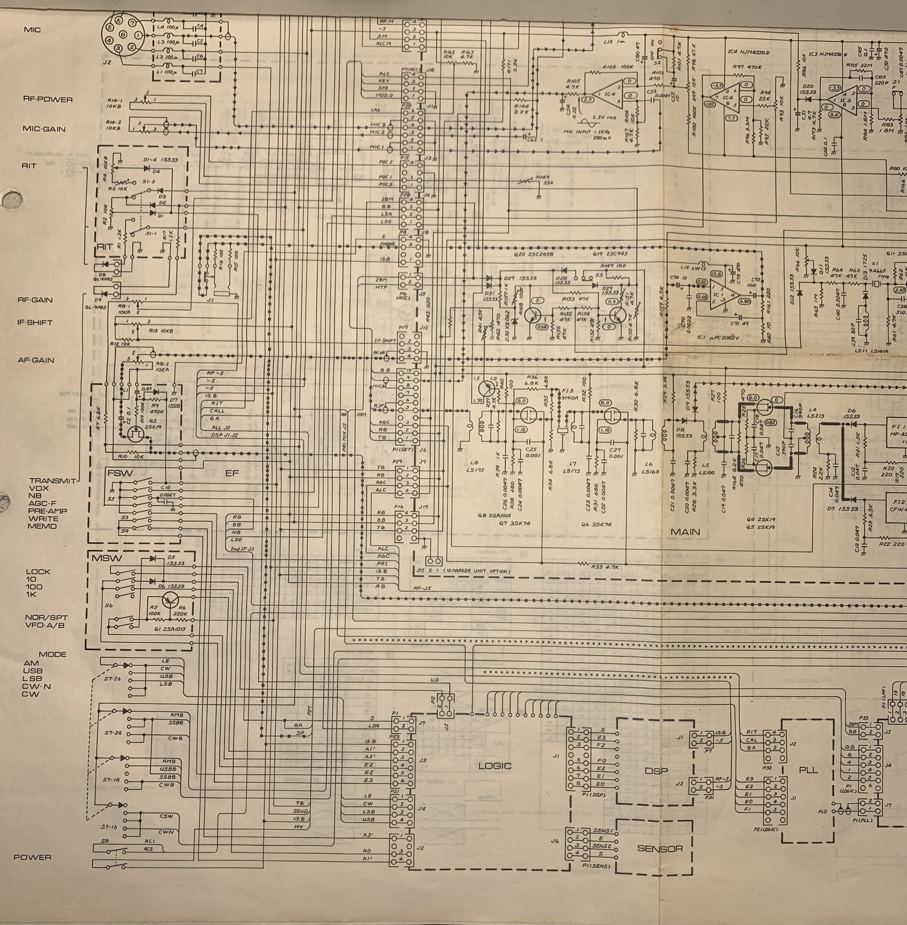
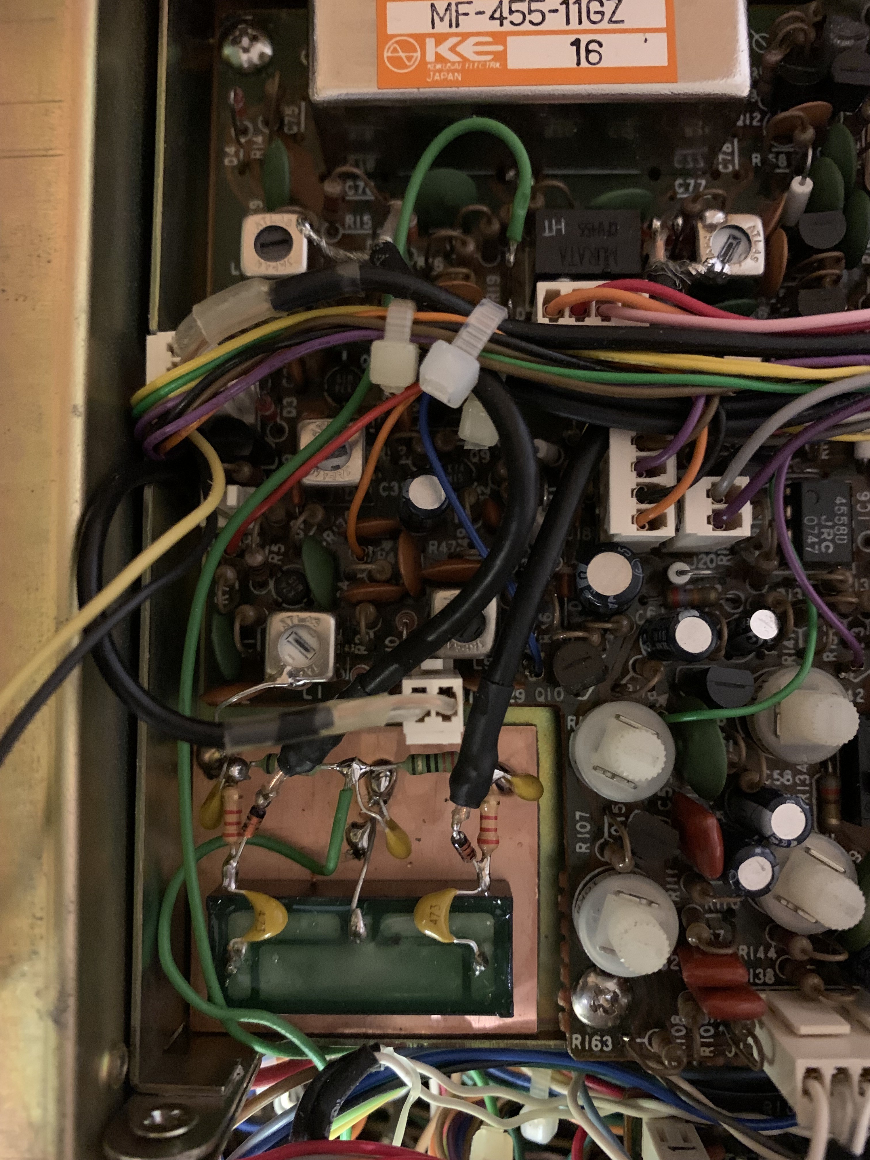
I installed the additional CW filter for the IC-730 in the location intended for the marker generator, since I don't use the marker in my IC-730. Please refer to the photo below. The circuit can be found in the accompanying diagram. It might be a bit confusing at first, so please use the original circuit diagram for reference and look at the circuit of the MAIN board. J13 is at the top left of the MAIN board circuit diagram. On the far left of the diagram, the front panel controls are drawn, including the MODE switch we're interested in.
And now all you basically need is a filter. I used the Yaesu XF-115C, a Collins mechanical filter with an impedance of 2000 ohms, which fits into the circuit without further measures. Add a small circuit for driving the 1N4148 switching diodes, and install the CW filter as shown in the picture below.
It really works fine, and for the CW operator, the effort is worthwhile.
Yaesu XF-115C installed
Schematic of the installation
MAIN PCB schematic