Project: SDR Receiver for CW Skimmer and the Reverse Beacon Network (RBN)
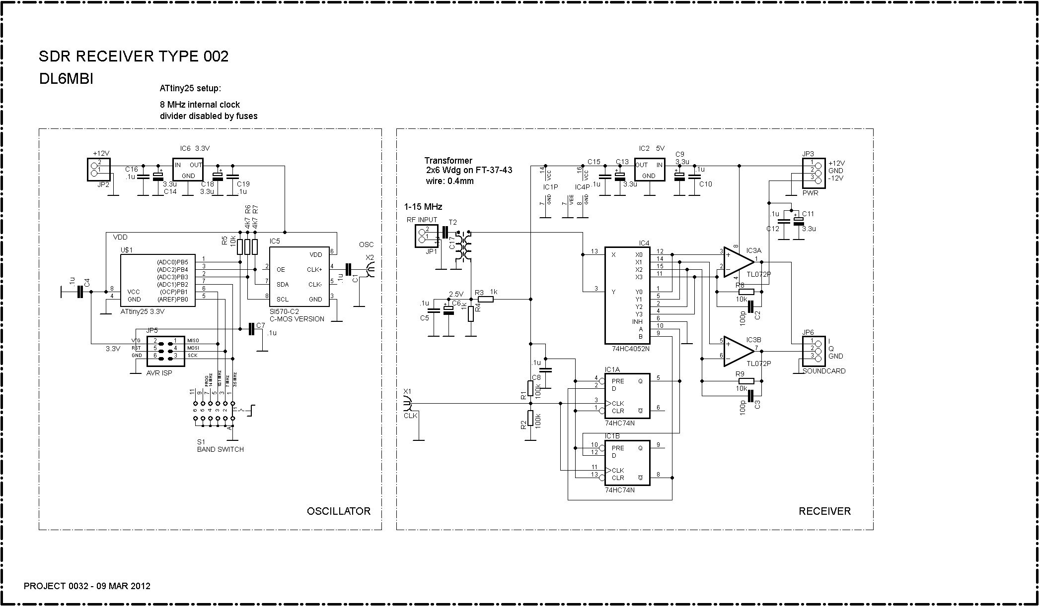
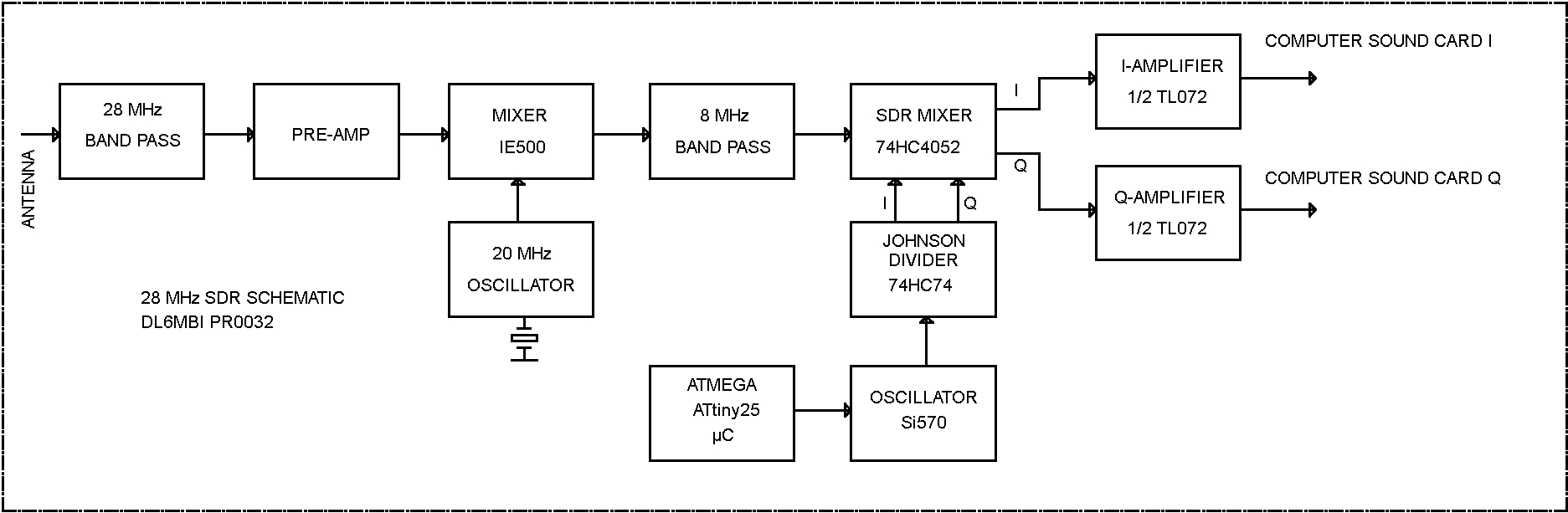
Here is my first attempt at an SDR receiver. It has a 74HC4052 mixer, which I found in my junk box. The oscillator is a CMOS version of a Silicon Labs Si570. It has enough output to drive a 74HC74 divider (1:4, 180°, driving the mixer). The sound card is an on-board type (SoundMAX, 48 kHz). The software is by VE3NEA (Rocky, CW Skimmer). This tiny receiver is very useful for 160–30 m operation, but I have also used it on 20 m.
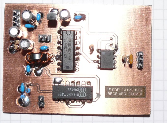
Receiver PCB:
- 74HC4052 mixer
- 74HC74 Johnson divider
- TL072 dual op-amp AF amplifier
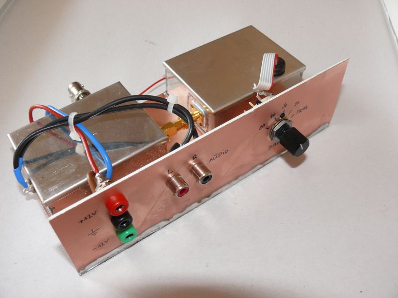
Complete experimental SDR receiver board:
- Right box: Silicon Labs Si570 (CMOS version) and Atmel ATtiny25 microcontroller
- Left box: SDR receiver
- Front: switch for 80/40/30/20 m operation, I/Q connectors, and 4 mm power supply connectors (+12 V / −12 V / 0 V)
How to Build an SDR
"SDR receivers" are usually direct-conversion receivers, so everything known about DC receivers must be taken into account. Good grounding, shielding, the best possible power supply, and a reliable computer sound card are necessary to get reasonable results. Avoid ground loops wherever possible! Some SDR receiver projects suffer because they disregard DC receiver fundamentals. Although the SDR in this picture uses an inexpensive mixer (74HC4052) and op-amps that are not the best for the purpose (TL072), it has remarkable performance!
If the oscillator is not properly shielded, it can radiate LO energy back into the connected antenna. This will certainly cause hum and intermodulation. To prevent this, always shield the oscillator in a metal housing. Do the same with the receiver. If you observe these fundamentals, you don't need expensive parts to be successful with your SDR project. Always use a hum-free power supply. Batteries are the best choice, although a good-quality power supply will do.
Notes:
- Some sound cards need decoupling capacitors (approx. 0.1 µF) at their inputs.
- One possible cause of malfunction with an Si570 oscillator is an impedance mismatch. If the Si570 does not work properly, I recommend trying a 100-ohm load at the signal output.
For 10 m operation, a barefoot SDR needs some extension. The 74HC4052 mixer used here performs acceptably up to a maximum of about 15 MHz. For 28 MHz operation, even devices faster than the 74HC4052 might not be fast enough for reliable results. Fortunately, there's a simple solution.
The performance of SDRs using "bus switch mixers" (the 74HC4052 in this case) degrades significantly with increasing frequency. Therefore, I designed a simple down-converter that converts the 28 MHz input to 8 MHz. At this frequency, the performance of the SDR is much better, even with fast-switching SDR mixers. The results of a 28/8 MHz down-converter in conjunction with the SDR described above and a simple on-board 48 kHz sound card are really impressive.
See more here:
- BASCOM code for the Si570 oscillator (80/40/30/20 m version)
- PCB layout for the 28 MHz down-converter (10 m version)
You need EAGLE to view the PCB; see the CadSoft website for more details. Feel free to send me an e-mail for assistance if you are not familiar with the EAGLE PCB software from CadSoft.
Example: my current SDR receiver project for Reverse Beacon Network operation on 28 MHz.
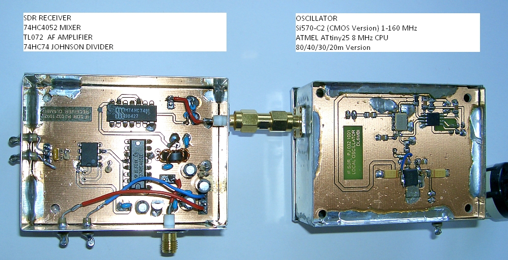
SDR receiver and oscillator (click on the picture for a larger view)
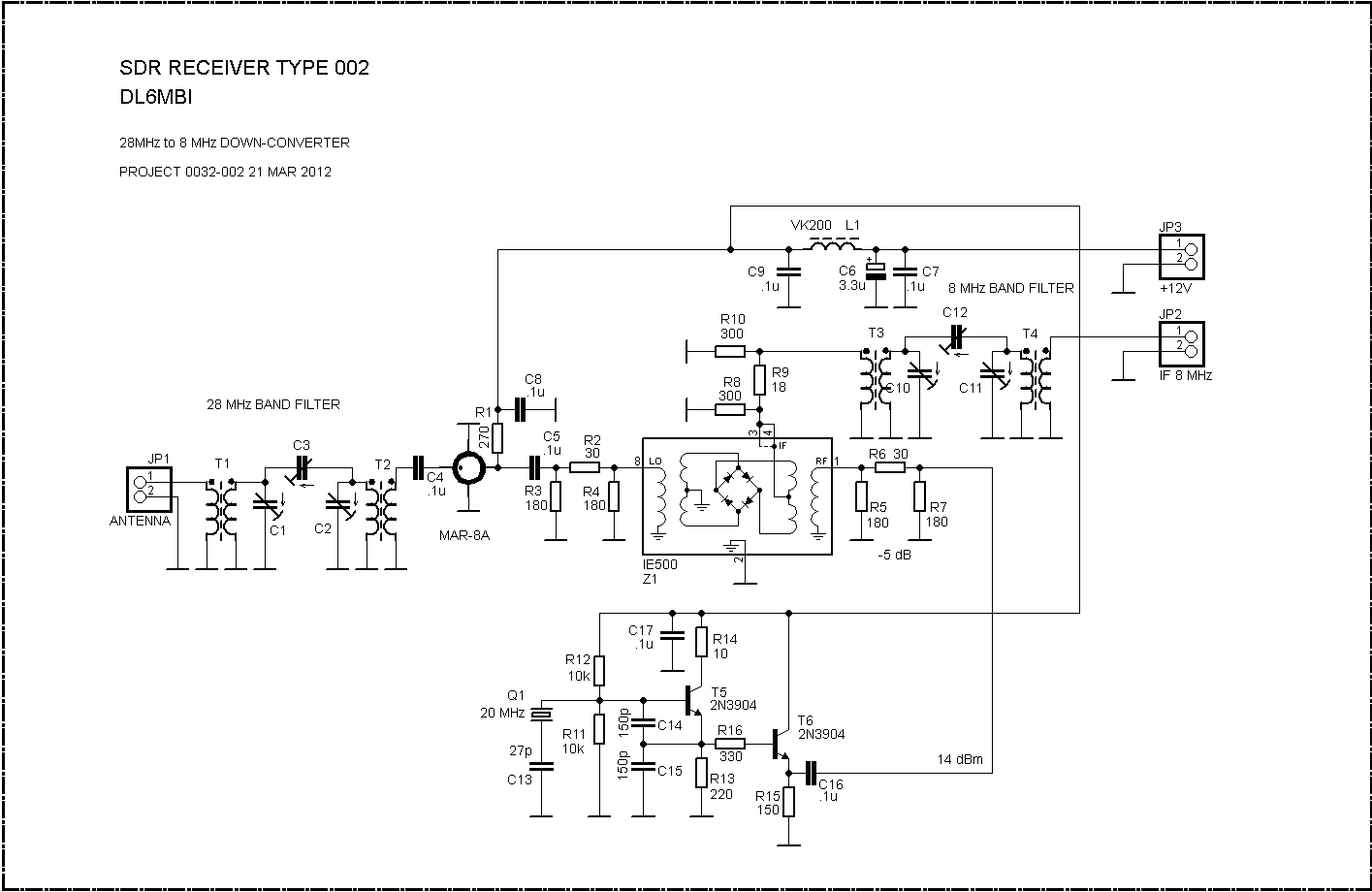
28 MHz down-converter (click on the picture for a larger view)
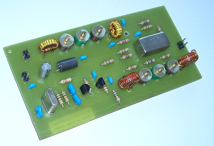
The SDR down-converter PCB has a "standard" size of 54 × 110 mm, which fits into a Schubert case no. 6.
The IE-500 mixer came from the junk box. Most other +7 dBm diode ring mixers (not all!) should be suitable.